PhysLab.net – Collisions With Contact
It may surprise you that getting objects to rest on the floor is a challenging problem! This simulation shows rectangular objects colliding in 2 dimensions. It is based on the rigid body collisions simulation, but it deals with steady contact forces where objects press against the floor, the wall or each other.Click near an object to exert a rubber band force with your mouse. With the keyboard you can control four "thrusters". The keys S,D,F,E control the gray object's thrusters. The keys J,K,L,I -- and also the arrow keys -- control the green object's thrusters. You can also set gravity, elasticity (bounciness), and damping (friction). You can choose from one to six objects. If you don't see the simulation try instructions for enabling Java. Scroll down to see the math!
Try rearranging the blocks so they lean against each other at various angles, or stacking the blocks. You'll see that they are very slippery and hard to get to stack! This is because there is no contact friction in this simulation.
The contact forces are shown as red lines that appear at the corners of the objects. Contact forces come in pairs that are equal and opposite, but only one of each pair is shown here.
About friction and damping: In this simulation, the contacts between objects have no friction whatsoever, so they can slide against each other easily. The damping parameter that you can modify (you may have to click on the "show controls" button to see the damping parameter) has to do with the motion of the objects through the space -- damping makes it as though the objects are moving through a thick syrup, or that there is friction between the background surface and the objects.
Why is this a challenging problem? Contact forces are tricky to figure out. Other forces are much simpler because they only depend on the position of one or two objects. For example, the force of a spring between two objects depends only on the position of the end points of the spring. But the contact forces between objects depends on all the other forces on the objects and how they rest against each other in a rather complex way.
How To Calculate Contact Forces -- Overview
The software (a class calledContactSim) described here for calculating contact forces works closely with software
that handles collisions, see Rigid Body Collisions.
That software (a superclass called Thruster5) takes care of collisions.
As a result there should be no collisions
occuring when the contact force code is active, because the collision code
detects collisions, backs up in time to just before the collision and
applies an appropriate impulse to cause the objects to bounce (it reverses
their velocities). The superclass also calculates the effects of
external forces acting on the objects
such as gravity, thrust, rubber band, and damping. (Interestingly, it is those external
forces that cause the contact forces: without them there would be
no forces pushing objects into each other.)The idea is to calculate the exact amount of force needed at each contact to just barely prevent the objects from penetrating. These forces are calculated in the
evaluate method of the ContactSim class, which is called repeatedly by the differential
equation solver to find the accelerations of the objects. The differential
equation solver uses that information to
advance the state of the world through time. On entering this evaluate method
we are given the current positions and velocities of each object, which is required
information for figuring out where contact points are and the geometry of
contact forces between objects.First we find all the resting contacts between objects. The criteria are: a corner must be very close to an edge and moving very slowly (in the direction perpendicular to the edge). Using these criteria, we assemble a list of contact points. For each contact, we store information such as: which are the two objects that are in contact, what is the normal (perpendicular vector) to the edge, where the point of contact is relative to each object, etc.
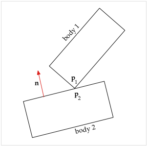
2 bodies in contact
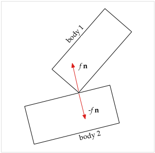
2 bodies with contact forces
We focus on the contact distance d, the gap between the points that are in contact. Because the objects are in contact, we have that d = 0 (within numerical tolerance). A value of d < 0 would indicate that the objects are interpenetrating. A value of d > 0 would indicate the objects are not in contact but separated by the distance d.
The rate of change of the contact distance is the velocity d'. Because the objects are in resting contact we have that d' = 0 (within numerical tolerance). This was one of the criteria for selecting the set of resting contact points. Note that the objects can be sliding against each other, because we only care about motion in the direction of the normal (perpendicular to the edge).
What we are most interested in is d'', the acceleration of the gap. Without contact forces we will find that d'' < 0 for most of the contact points, meaning that without any contact force, the objects will fall into each other and interpenetrate.
What makes computing the contact forces somewhat tricky is that they are all interrelated. This is because you can have a complex arrangement of objects resting on each other. The solution involves finding a set of equations that captures exactly how each contact force affects each gap. Then we solve the equations to find forces that exactly set d'' = 0 at each contact point. Actually, we also allow d'' > 0 which means the objects are separating and therefore there is no contact force at that particular contact.
Once we have found the exact force at each contact that will preserve the resting contacts (keeping the objects from accelerating into each other) we then apply those forces to each object. This results in changes to the accelerations of the objects. We then return control to the differential equation solver which continues to evolve the simulation over time using those new accelerations. But now the accelerations are modified so that the objects will remain in resting contact as desired.
Calculating Contact Forces -- in Detail
This software (theContactSim class) for calculating contact forces is a subclass of the
Rigid Body Collisions software (the Thruster5 class). The following
description builds on the explanations at that web page, particularly for
the external forces.
The algorithms used here are based on two papers by David Baraff:[Baraff-1] David Baraff, An Introduction to Physically Based Modeling: Rigid Body Simulation II - Nonpenetration Constraints. These are lecture notes from Physically Based Modeling: Principles and Practice (Online Siggraph '97 Course Notes).
Note that there is a typographic error on page D62: in several places where you see "a force of j nj(t0)" it should read "a force of fj nj(t0)".
[Baraff-2] David Baraff. Fast contact force computation for nonpenetrating rigid bodies. Computer Graphics Proceedings, Annual Conference Series: 23-34, 1994. 12 pages.
Assume that we have a set of n contacts in some particular (but arbitrary) order. Define the following variables:
- n = number of contacts.
- di'' = acceleration of contact distance of the i-th contact.
- a = length n vector of accelerations of contact distances, so that ai = di''
- f = length n vector of contact force magnitudes (to be determined)
- b = length n vector giving contact distance accelerations due to external forces (gravity, thrust, etc.)
- A = an n × n matrix that specifies how contact forces affect acceleration of contact distances
- ai j = the element of A in the i-th row and j-th column.
| a = A f + b | (1) |
| di'' = ai 1 f1 + ai 2 f2 +. . . + ai j fj + . . . + ai n fn + bi | (2) |
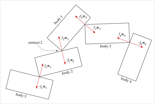
5 bodies, 4 contact points, 8 contact forces
To illustrate how the A matrix and the b vector are calculated, consider the figure above. We have 5 bodies which are in resting contact at 4 contact points and the resulting contact forces are shown. (Note that the normals ni are always perpendicular to an edge and by convention point out from the object; this determines which forces have minus signs). The contact points are numbered in accord with the contact forces, so that contact force f1 n1 is at contact 1, etc. Focusing on contact 2 (between bodies 1 and 2), from equation (2) we can write
| d2'' = a2,1 f1 + a2,2 f2 + a2,3 f3 + a2,4 f4 + b2 | (3) |
- For all the non-contact forces (gravity, thrust, etc.) currently acting on body 1, we calculate what is the resulting acceleration of the corner of body 1 at contact 2; this is added in to b2.
- Similarly, for all the non-contact forces (gravity, thrust, etc.) currently acting on body 2, we calculate what is the resulting acceleration of the point on body 2 at contact 2; this is added in to b2.
- Regarding contact force f1 n1, for a unit change in f1 we calculate what would be the resulting acceleration of the point on body 2 at contact 2; this is put in a2,1.
- Regarding contact force f2 n2, for a unit change in f2 we calculate what would be the resulting acceleration of the corner of body 1 at contact 2; this is put in a2,2.
- Regarding contact force −f2 n2, for a unit change in f2 we calculate what would be the resulting acceleration of the point on body 2 at contact 2; this is added to a2,2.
- Regarding contact force −f3 n3, for a unit change in f3 we calculate what would be the resulting acceleration of the corner of body 1 at contact 2; this is put in a2,3.
- Because contact forces f4 n4 and −f4 n4 do not directly affect bodies 1 or 2 we set a2,4 = 0.
Once we have found the A matrix and b vector, we are ready to solve equation (1) for the unknown force magnitudes in the f vector, subject to the following 3 constraints:
| ai >= 0, fi >= 0, a · f = 0 | (4) |
- ai >= 0 means we disallow interpenetration (which occurs when ai < 0). We require all the relative normal accelerations between bodies at contact points to be either zero (in contact) or positive (separating).
- fi >= 0 means we require contact forces to be zero or positive because they can only push, not pull.
- a · f = 0 means that, at every contact point, if there is a contact force then acceleration is zero OR if there is acceleration (separation) then there is no contact force. The dot in the equation is the vector dot product.
The algorithm begins by setting all the contact forces in f to zero. The basic idea is to add in one contact force at a time, adding just enough force to maintain the constraints, and readjusting the other forces as necessary. We ignore the contact points we haven't yet considered, gradually increasing the set of contact points that obey the constraints. Here is a very simplified sketch of how it works:
- Begin by considering only contact 1, ignoring all other contact points (which are likely violating the constraint that ai >= 0). We calculate the amount of force f1 at contact point 1 which is just sufficient to make a1 = 0.
- Next add in contact 2. Solve for f2, adjusting f1 as necessary, so that the three constraints are valid for a1, a2 and f1, f2.
- Continue adding in contacts and contact forces one at a time, while adjusting previous forces as necessary to maintain the three constraints (4).
Now that we know the contact forces, the last step is to apply them to the bodies, which gives the final set of body accelerations that the
evaluate method then returns to the differential equation solver.
The geometry of where each contact force is applied on each body comes into play
here to determine how that contact force affects the linear and angular acceleration
of a given body. This process is very similar to that described on the Rigid Body Collisions web page for treatment of forces such as the thrust force.The differential equation solver then continues to evolve the simulation over time using those new accelerations. These accelerations have however been precisely calculated so that the bodies that are in resting contact remain in resting contact without interpenetrating.
Calculating the A Matrix
Our goal here is to calculate the entries of the A matrix of equation (1). As described above, the i, j-th entry in the A matrix, ai j, specifies how the j-th contact force, fj, affects the acceleration of the i-th contact distance, di''.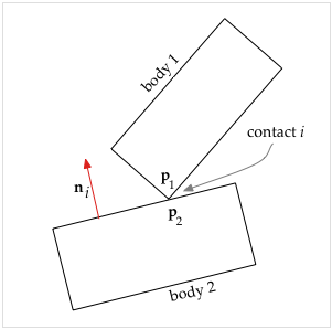
2 bodies in contact
| di = ni ⋅ (p1 − p2) | (5) |
di'' = ni'' ⋅ (p1 − p2) + 2 ni' ⋅ (p1' − p2') + ni ⋅ (p1'' − p2'') Because this is a point of contact, we have that p1 − p2 = 0 so the above simplifies to
| di'' = ni ⋅ (p1'' − p2'') + 2 ni' ⋅ (p1' − p2') | (6) |
| ni ⋅ (p1'' − p2''). | (7) |
Let nj be the vector normal at the j-th contact point. Assume that the j-th contact involves body 1. Then the contact force is fj nj if the contact involves a corner of body 1 or −fj nj if the contact involves an edge of body 1. From the geometry we can calculate the effect of the force on body 1, and therefore on the acceleration of p1''. If the contact involves body 2, then the effect is on p2''. Then using equation (7) we will arrive at the contribution of fj nj to ai j.
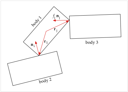
3 bodies in contact
- x1 = center of mass of body 1
- r1 = vector from center of mass of body 1 to p1 at the i-th contact point
- rj = vector from center of mass of body 1 to the j-th contact point
- ω1 = magnitude of the angular velocity of body 1
- ω1 = angular velocity of body 1, a vector that is perpendicular to the plane, so ω1 = {0, 0, ω1}.
- v1 = x1' = velocity vector of center of mass of body 1
- m1 = mass of body 1
| p1' = x1' + r1' = v1 + ω1 × r1 | (7a) |
| p1'' = v1' + ω1' × r1 + ω1 × (ω1 × r1) | (8) |
| v1' + ω1' × r1 | (8a) |
Because v1' is the linear acceleration of body 1, we have by Newton's First Law v1' = (total force on body 1) /m1 Therefore the fj dependent part of v1' is fj nj /m1 Because we are working in 2D, we can write angular acceleration as ω1' = τ1 / I1 where τ1 = torque on body 1, and I1 = rotational inertia of body 1 about the center of mass. (If you are working in 3D, angular acceleration has another term; see [Baraff-1] for more information). Suppose that the j-th contact occurs at the point pj, and the vector rj goes from center of mass of object 1 to pj. Then the force fj nj contributes a torque of rj × fj nj. So the fj dependent part of ω1' is (rj × fj nj) / I1 and we can write equation (8a), the fj dependent part of p1'', as fj nj / m1 + (rj × fj nj) × r1 / I1
= fj (nj / m1 + (rj × nj) × r1 / I1) and the fj dependent part of di'' in equation (6) is then fj ni ⋅ (nj / m1 + (rj × nj) × r1 / I1) Therefore, looking back at equation (2) for context, we have the dependence of di'' on fj as
| ni ⋅ (nj / m1 + (rj × nj) × r1 / I1) | (9) |
Keep in mind that we assumed that fj nj affected body 1. If instead it is −fj nj affecting body 1, then that changes the sign of expression (9). If fj nj affects body 2 instead of body 1, then the effects are on p2'' in equation (6), so there is a sign change and also we use m2, r2, and I2 in expression (9) and rj is computed relative to body 2. Also, in the case where fj nj is at a contact point between bodies 1 and 2, then fj nj affects body 1 and −fj nj affects body 2 and you wind up using expression (9) twice and putting the sum in ai j.
Calculating the b Vector
Here we calculate the b vector of equation (1). The b vector specifies what the contact distance acceleration di'' would be in the absence of contact forces. It depends on non-contact forces such as gravity, thrust, rubber band force, damping, etc., but also has a velocity dependent component.Note that it is these forces that cause the contact forces to exist; the contact forces develop in reaction to the other forces that are pushing the objects together, so contact forces are also known as "reaction forces".
In the context of solving equation (1), the b vector is regarded as a "constant" vector, because at the moment in time that we are solving equation (1) for the contact forces, the b vector is a known quantity.

2 bodies in contact
Derivation of ni'.
Recall that ni is the normal vector to body 2 in the scenario of the previous section. We know that body 2 is rotating with angular velocity ω2. Therefore, by an elementary bit of calculus we can write ni' = ω2 × ni where we treat angular velocity as a vector ω2 perpendicular to the plane so that ω2 = {0, 0, ω2} Here is the derivation of that result: Let ni be defined as follows (because we are in 2D the z component is zero): ni = {nix, niy, 0} We know that the vector ni is rotating at a rate ω2. Ignoring any acceleration, we could write the vector ni as a function of time like this: ni = |ni| {cos(ω2 t), sin(ω2 t), 0} Where |ni| is the magnitude of the vector ni, and t = time. The first derivative is then ni' = |ni| {−ω2 sin(ω2 t), ω2 cos(ω2 t), 0} which is equivalent to: ni' = {−ω2 niy, ω2 nix, 0} which can also be expressed as a cross product of the two vectors: ni' = ω2 × ni
Now we can use that expression for ni' and equation (7a) which gives an expression for p1' (and similarly for p2' as well) to write that
| 2 ni' ⋅ (p1' − p2') = 2 (ω2 × ni) ⋅ (v1 + ω1 × r1 − (v2 + ω2 × r2)) | (10) |
Next consider the term ni ⋅ (p1'' − p2'') of equation (6). We need to include in bi the effect of any non-contact forces on the accelerations of the contact points p1 and p2. We will start from equation (8) which was derived in the previous section: p1'' = v1' + ω1' × r1 + ω1 × (ω1 × r1) It turns out that the accelerations v1' and ω1' that are due to non-contact forces have already been calculated for us by the earlier processes (see
evaluate method of Thruster5 class).
Those accelerations are passed in to our evaluate method and so we
simply plug them into equation (8) to get p1'' (and p2'' has the similar expression).
So we can write this out as
| ni ⋅ (p1'' − p2'') = ni ⋅ (v1' + ω1' × r1 + ω1 × (ω1 × r1) &minus (v2' + ω2' × r2 + ω2 × (ω2 × r2))) | (11) |
We now have in expressions (10) and (11), the contact-force-independent parts of equation (6) which is what goes into bi.
|
|
� Maria Kovalenko, 2007 | PhysLab | Top |
Next |